Design of Mechanical Vise
- Saurabh More

- Jun 7, 2020
- 1 min read
Aim
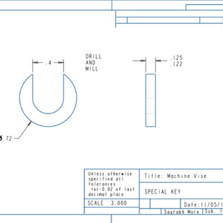
1. To Create the machine vise assembly shown in attached PDF. Assemble the components into the assembly with at least one sub-assembly. Create a solid model for each of the twelve parts from the dimensions shown in the PDF. Use standard components from the CREO library whenever appropriate. Estimate, using engineering judgment, any dimensions not given. Chamfer, fillet, or round where required for a well-designed component. Detailed drawing of each part should be provided.
CAD Modeling - PTC CREO


Detailed Drawings for each part are shown below


Comments